Pcb Design Using Easyeda
Published 5/2023
MP4 | Video: h264, 1280x720 | Audio: AAC, 44.1 KHz
Language: English | Size: 1.67 GB | Duration: 1h 57m
Published 5/2023
MP4 | Video: h264, 1280x720 | Audio: AAC, 44.1 KHz
Language: English | Size: 1.67 GB | Duration: 1h 57m
Powerful, easy and user friendly PCB design software used by students, professional, maker and ethusiastic people.
What you'll learn
Basics of Printed Circuit Board
Schematic and circuit design
Selection of Components
Routing and layout
Design rule check
Generate Gerber files
How to order the pcb from the gerber files
Requirements
No prior experience as such but good to have basics of electronic
Description
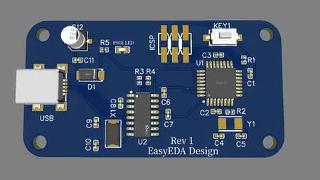
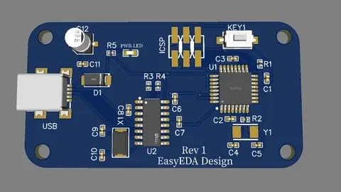
After completing this course I am pretty much sure that you will be able to design your own printed circuit board. This course is a 2 hour course with instructed lectures and explanation on each topic. This course is designed for students, engineers, electronics makers and professionals or anyone interested in making the university projects. Do not need any software to download as we will use the online PCB editor in this course. We will guide you to the entire process of Printed circuit board design.The Topic which are covered1. Introduction to PCB design: Learn what is PCB and the different terminologies used in the PCB. Differentiate between through hole and smd components. Step by step instruction on how to design a PCB. Use the Free EasEDA software in this course. We will also see the EasEDA interface on the webbrowser. You will just need a Webbrowser with and active internet connection.2. Schematic Design: Convert the circuit design to the Schematic design. Select components and do the connection. Perform electrical rule check after completing the schematic. This is the first step in PCB design and it should be correct to make it work.3. PCB design and Layout: convert the schematic design to the PCB. Learn how to place the components/footprint according to the schematic design. Route the tracks using the autorouting feature of the EasyEDA tool. Perform design rule check based on the rules defined. 4. Gerber files and BOM: After completing the design, then generate the gerber files or the output files. This gerber files are given to the PCB manufacturer to manufacture this PCB according to the design.If you have build some circuit on breadboard and want to convert it to a PCB then this you are at the right place. We will teach you how you can convert the circuit design to the schematic design and then convert them to Printed circuit board. Manufacture those PCBs and after that you can physically solder the components and test those PCBs.
Overview
Section 1: Introduction
Lecture 1 Introduction : Basics of PCB
Lecture 2 PCB Terminologies
Section 2: Schematic Design
Lecture 3 Getting hands on with the EasyEDA tool : First Project
Lecture 4 Schematic Design of Microcontroller circuit
Lecture 5 Schematic Design of CH340 IC and Other Circuit
Section 3: PCB design and Layout
Lecture 6 Placement of Components
Lecture 7 Routing and Layout
Lecture 8 Copper Pour and 3D viewer
Lecture 9 Working with silkscreen layer
Lecture 10 Design Rule Check
Section 4: Gerber files and BOM files (OUTPUT Files)
Lecture 11 Gernerating Bill of materials and gerber files
Lecture 12 Uploading files to the PCB Manufacturer
Students, teachers, makers and professionals,Electronics enthusiastic


