
Autodesk Inventor 2018.1 Update
Autodesk Inventor 2018.1 Update | 377.2 mb
Autodesk Inc., a world leader in 3D design software for entertainment, natural resources, manufacturing, engineering, construction, and civil infrastructure, has released an update (SP1) to Inventor 2018. The release introduces a series of new features and improvements to the mechanical design and 3D CAD software.
It’s that time when Autodesk releases another version of Inventor. I’m taking Inventor 2018 out for a test drive and sharing what it has to offer. Although there are many new enhancements, my personal top three are the new measurement tool, followed by the updated browser interface, and a close tie for third place are the 3D Annotation (or Model-Based Definition – MBD) for parts and ANYCAD for Inventor.
What's New for Inventor 2018.1
Interoperability
- AnyCAD for Solid Edge
You can now import Solid Edge files with an option to convert or create an AnyCAD reference. Importing a Solid Edge file as an AnyCAD reference model maintains a link to the selected file which enables you to monitor and update as the model changes. You can also use Task Scheduler to automate importing multiple Solid Edge files.
Parts
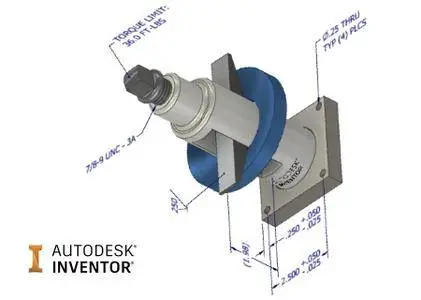
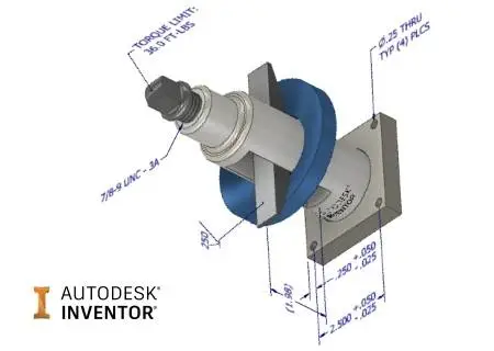
- Model-Based Definition
Support for the following modifiers was added to Tolerance Feature annotation: Free State, Projected Tolerance Zone, Statistical, Tangent Plane, Unequally Disposed. Annotation scale control is added in sheet metal flat pattern.
Sketch
- Project Geometry as Construction Geometry by Default
You can make projecting geometry as construction geometry the default behavior with the new setting in the Application Options dialog box on the Sketch tab: Project objects as construction geometry. With this option selected, you do not have to continually toggle the Construction command on when creating sketch geometry. When this new setting is selected, every time you project geometry, the geometry is projected as construction geometry. By default, this option is deselected.
- Auto Project Geometry when Dimensioning or Constraining a Sketch
Previously when you added dimensions or constraints to sketch geometry with a work axis or work point, you had to use the Project Geometry command to first project the selected work axis or work point.
Now when you select an axis or point outside of the sketch you are dimensioning or constraining, the selected work axis or work point is automatically projected when you add dimensions or constraints.
Assemblies
- 3D Annotation for Assemblies
A new Annotate tab is added to the ribbon in the assembly environment. The new tab contains commands that let you add dimensions, notes, and other information to your assembly.
- Task Scheduler > Shrinkwrap Assemblies
The shrinkwrap task now includes the new shrinkwrap functionality introduced in 2018. When you click Options, the Shrinkwrap Options dialog now has three tabs.
. Components tab contains the document level information such as representations and removing components by size.
. Features tab contains the choices for easily defining which features to remove from the shrinkwrap part. You can retain specific feature types, remove them, or remove them by a range value.
. Create tab contains the file-related information, shrinkwrap style, and other settings.
Highlights of the new workflow:
. Remove parts by size by specifying the Max. Bounding Box Diagonal.
. Fine control over removal of holes, pockets, fillets, and chamfers. You can choose to preserve, remove all, or remove within a . specified range size.
- Bill of Materials Thumbnail Enhancement
Thumbnail images are now exported along with the other information in the Bill of Materials dialog box. The Thumbnail column must be included as a column in the Bill of Materials dialog box for the thumbnails to export to the external file.
- Add Participant and Weld Bead Enhancement
You can now select a weld bead from a sub-assembly to add as a participant in an assembly feature in the top assembly when the weld bead is added after you create an assembly feature.
- Other Assembly Enhancements
In an assembly, when you constrain a component on one axis to sketch geometry on a different axis, the component will be now be placed at a point on the axis closest to the selection point needed to satisfy the constraints on the component. Previously, the component might be placed outside of the graphics window.
Drawings
Drawing view updates now occur faster due to a change in how view edits are processed. In response to 3D model edits, drawing views update only the portion of the view that has changed.
General
iLogic Productivity Improvements
New Robust Events Trigger Workflow
The Rules Triggered by Events dialog box is replaced by the new Event Trigger dialog box:
- Rules defined under External Rule Directories in the iLogic Configuration dialog box display under External Rules in the new Event Trigger dialog box.
- Quickly assign external event triggers to multiple file types. Select a tab, and then drag and drop a rule under External Rules to an event.
- Use the Parts, Assemblies, Drawings tabs to manage document type specific rules.
- Use the new file, RulesOnEvents.xml, to manage external rules.
. RulesOnEvents.xml stores the external triggers for All documents, Parts, Assemblies, and Drawings.
. RulesOnEvents.xml is located in the first External Rules Directory as specified in the iLogic Configuration dialog box.
. You can share the file on a network drive.
Exchange App Manager is Renamed to Autodesk App Manager
- Access the Autodesk App Manager From the ribbon: Tools tab Options panel Autodesk App Manager.
Other General Enhancements
- When you close a part or assembly file that you have made no changes to in the Stress Analysis environment, you are no longer asked you if you want to save the changes before closing.
- The performance issue loading Thread/Clearance data is resolved. Inventor now reads the Excel spreadsheet for Thread or Clearance data using the Excel libraries, and no longer loads Excel even when Excel is installed on the local machine.
Attention: The environment variable UseLibXL is no longer required, and should be removed from your system as it can prevent Excel from being used for table write operations.
- A new help topic is created to explain Inventor Save and Check out Requirements. This topic will continuously be updated as additional workflows are identified.
About Autodesk
Autodesk is a world-leading supplier of engineering software, providing companies with tools to experience their ideas before they are real. By putting powerful Digital Prototyping technology within the reach of mainstream manufacturers, Autodesk is changing the way manufacturers think about their design processes and is helping them create more productive workflows. The Autodesk approach to Digital Prototyping is unique in that it is scalable, attainable, and cost-effective, which allows a broader group of manufacturers to realize the benefits with minimal disruption to existing workflows, and provides the most straightforward path to creating and maintaining a single digital model in a multidisciplinary engineering environment.
Product: Autodesk Inventor
Version: 2018.1 Build 171 Update
Supported Architectures: x64
Website Home Page : www.autodesk.com
Language: english
System Requirements: PC
Supported Operating Systems: Windows XP / Vista / 7even / 8.x / 10
Software Prerequisites: Autodesk Inventor 2018
Size: 377.2 mb
Please visit my blog
Added by 3% of the overall size of the archive of information for the restoration
No mirrors please

![Autodesk Inventor 2018.1 Update]()
Added by 3% of the overall size of the archive of information for the restoration
No mirrors please
Autodesk Inventor 2018.1 Update