

STAAD.Pro V8i SS6 version 20.07.11.90

STAAD.Pro V8i SS6 version 20.07.11.90 | 683.9 mb
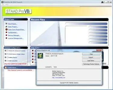
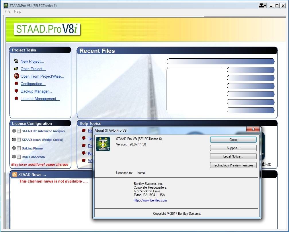
Bentley Systems Inc., the leading company dedicated to providing comprehensive software solutions for sustaining infrastructure, has released the V8i (SELECTSeries 6) 20.07.11.90 version of STAAD.Pro is a comprehensive and integrated finite element analysis and design offering, including a state-of-the-art user interface, visualization capabilities, and international design codes.
STAAD.Pro V8i SS6 version 20.07.11.90
Design any type of structure and share your synchronized model data with confidence among your entire design team, using STAAD.Pro. Ensure on time and on budget completion of your steel, concrete, timber, aluminum, and cold-formed steel projects, regardless of complexity. You can confidently design structures anywhere in the world using over 80 international codes, reducing your team’s need to learn multiple software applications. Thanks to the flexible modeling environment and advanced features such as dynamic change revisions and management, you can:
- Lower total cost of ownership: Design any type of structure including culverts, petrochemical plants, tunnels, bridges, and piles
- Increase design productivity: Streamline your workflows to reduce duplication of effort and eliminate errors
- Reduce project costs and delays: Provide accurate and economical designs to your clients and quickly turnaround change requests
STAAD.Pro V8i SS6 version 20.07.11.90
(A) Issues addressed in the Analysis/Design engine (45)
A) 01 The AS 4100-1998 code has been updated to include a modification for clause 6.3.3 such that flexural torsional buckling for sections outlined in the clause updated in Amendment 1 now follow the method outlined in AS4600.
A) 02 The design of PMEMBERS in the AS 4100 design routine has been modified such that if there is an issue with the design strength FYLD, then this is now reported once for the member rather than once for each analytical beam which is part of the PMEMBER.
A) 03 The AS 4100 steel design for physical members has been improved to catch the situation where a PMEMBER has been specified section properties to the individual analytical parts (rather than the PMEMBER itself (the recommended approach) and the different parts have been assigned differing section profiles. This will now be trapped and an error message reported.
A) 04 The AS 4100 steel design has been corrected to ensure that the calculation of Mox,c is determined from the member end that has the largest axial force, rather than simply taking the value from the end of the member.
A) 05 The AS 4100 steel design routines have been improved in determining the effective area of wide flange sections that are classified as non-compact or slender.
A) 06 The AS 4100 steel design module has been enhanced with a wider selection of steel grades as defined in the standard.
A) 07 The AS 4100 steel design module has been enhanced to include checks for interaction of shear and bending using the interaction method as per clause 5.12.3
A) 08 The AS 4100 steel design for PMEMBERS has been updated to ensure that the PBRACE command can process lists in the form "a TO b"
A) 09 The output reporting for PMEMBERS designed to the AS 4100 steel design code has been improved to include the slenderness details.
A) 10 Further to A) 09, should a PMEMBER designed to the AS 4100 steel design code fail the slenderness checks, then this is now reported in the output file and confirms that no further checks can be performed.
A) 11 Further to A) 10, should a PMEMBER designed to the AS 4100 steel design code fail the slenderness checks, the governing criteria is now reported as 'Slenderness'. Previously in this situation the governing criteria was left blank.
A) 12 The AS 4100 steel design of web tapered members has been improved to include the effect of clause 6.3.4 in determining the member compression capacity. In order to determine the value of 'Nom', an assumption is made that the profile is prismatic and uses the expression from clause 4.6.2, using the shallowest profile of the tapered member which is on the conservative side.
A) 13 The AS 4100 steel design routines have been enhanced by adding the alternative method for determining the nominal in plane member moment capacity, Mi as defined in clause 8.4.2.2 for doubly symmetric I sections and rectangular and square hollow sections.
A) 14 The AS 4100 steel design routines have been enhanced by adding the alternative method for determining the nominal out-of-plane member moment capacity, Mox as defined in clause 8.4.4.1 for doubly symmetric I sections without transverse loading.
A) 15 The AS 4100 steel design routines have been corrected to ensure that Mix and Miy are calculated when there are moments in EITHER direction. Previously, these were only being calculated if the was an axial compression and moments in BOTH directions.
A) 16 The AS 4100 steel design routines have been enhanced with alternative expression for the biaxial bending check as per section 8.3.4 for doubly-symmetric I-section, rectangular and round hollow sections.
A) 17 The AS 4100 steel design routines for calculating the nominal section moment capacity reduced by the axial tensile or compressive force as defined in section 8.3.3(a), for doubly symmetric compact I sections has now been implemented when working with members subject to single axis bending about their minor axis.
A) 18 The AS 4100 steel design routines for calculating the nominal section moment capacity reduced by the axial tensile or compressive force as defined in section 8.3.2(a), for doubly symmetric compact I sections has now been implemented when working with members subject to single axis bending about their major axis.
A) 19 The AS 4100 steel design routine has been improved for determining the minor axis shear capacity for welded wide flange sections such as WB or WC, so that it now only uses the depth between flanges rather than the overall depth which is used for rolled sections.
A) 20 The design of PMEMBERS to the AS 4100 steel design code where the load has been defined as assigned on the top flange (i.e. LHT=1), has been corrected to ensure that the value of kl is determined from table 5.6.3(2) depending on the restraint.
A) 21 The design of PMEMBERS to the AS 4100 steel design code has been corrected to ensure that the value of the ALB parameter is correctly assigned to the physical member.
A) 22 The steel design routines for AISC 360, IS800 and CSA S16, were liable to crash if the file included a SELECT command which had a list that included plates as well as members. This situation is now trapped and the plate numbers will not cause the design to fail.
A) 23 The AISC 360 steel design deflection check routine has been updated to ensure that if a member SELECT is used, the calculations used in the output are based on the final section property.
A) 24 The IS800-2007 steel design deflection check routine has been updated to ensure that if a member SELECT is used, the calculations used in the output are based on the final section property.
A) 25 The CSA S16 steel design deflection check routine has been updated to ensure that if a member SELECT is used, the calculations used in the output are based on the final section property.
A) 26 Further to A) 05, the AS 4100 steel design routines have been improved in determining the effective area of wide flange sections that are classified as non-compact or slender.
A) 27 The steel design routines that perform a deflection check have been updated to catch a situation where an internal element array would overflow and cause the analysis to crash.
A) 28 The AISC 360 steel design for tapered members has been updated to ensure that clause H2-1 is correctly determined and reported.
A) 29 The deflection check performed in the AISC 360 routines for cantilever members has been updated to ensure that the values of deflection in each of the three local axes are extracted from the model correctly.
A)30 The IS 800-2007 steel design routine has been updated to ensure that if the section database for channel profiles includes the value of Ct, that is the distance from the back of the web to the centroidal axis, then that value is used directly. Previously this value was being calculated from the section dimensions even if it existed in the database.
A) 31 The Aisc ASD - 9th edition steel design routines for calculating the bending capacity Fb for web tapered members defined as I-Section UPT profiles, where the flanges have different dimensions, have been modified to ensure that rt accounts for the flange that is in compression.
A) 32 The BS 5950 steel design routines have been updated to extend the design of tubes and pipes to include SHS, RHS and CHS profiles.
A) 33 The IS 800 2007 LSD has been updated to improve the determination of the section capacity for members under very high shear where V/Vz>0.6, an additional check has been introduced which limits beta-y to 1.0
A) 34 The BS 5950 steel design routine has been updated to ensure that rectangular and circular section profiles that are not supported are reported as such in the design output.
A) 35 The BS 5400 steel design routine has been updated to improve the routine that determines the gross sectional area of a wide flange that has been specified in a UPT and can have different flange dimensions. Previously, the gross sectional area would have been determined using the dimension of the top flange as that for the bottom flange.
A) 36 The NS 3472 steel design module has been updated to ensure that if a member has been assigned a non-supported profile for this code, then a warning message is posted in the user report. Note the previously some section profiles would appear to have been designed, but in the post processing>Beam>Steel Design would show the ratio as '1#QNAN'
A) 37 The EN 1993-1-1 steel design routine has been enhanced with an additional test on a UPT General Sections. This will design the member as a shape based on the GST parameter. However, if the UPT profile does not have sufficient dimensional information data, then this will report as an error in the design output.
A) 38 The Aisc ASD - 9th edition steel design routines for calculating the allowable compression capacity Fa (section Appendix B5.) for web tapered members defined as I-Section UPT profiles which have slender elements and where the flanges have different dimensions, have been modified to ensure that Qs accounts for the actual flange dimensions, and no longer uses an average flange size.
A) 39 The AISC ASD - 9th Edition steel design routines have been updated to improve the design of wide flange sections which have differing sized flanges. The program will now check to identify which is the compression flange and use the elastic modulus for that rather than simply picking the smallest elastic modulus which could lead to an overly conservative design.
A) 40 The torsion checks with AISC 360 steel design to Design Guide 9 (DG9) has been updated to catch if any load combination is defined with a dynamic primary load case. This is currently outside the scope of this routine and if any such cases were included would cause the analysis to crash.
A) 41 The IS 800-2007 steel design routines for web tapered members have been updated to ensure that the details of the web classification are reported for the critical location on the member rather than the profile at its start location.
A) 42 The concrete design routines for IS 13920 have been updated to trap the occurrence of using a load combination for the gravity load case (defined with the GLD parameter), which is a combination case that itself references a separate load combination. Previously, if such a load combination had been used, this would result in a crash of the analysis. At this time rather than using an included combination, it is suggested to create an equivalent primary load case and use the REPEAT LOAD method instead.
A) 43 The ASME NF design codes have been updated with the addition of a check to clause NF-3322.(d)(1)(6)-12 for determining the calculation of allowable bending stress for box sections. Now when the value of L > Lc, then the allowable capacity is calculated as 0.6Fy rather than 0.66Fy.
A) 44 The steel design routines to AS 4100 have been improved to ensure that when determining the slenderness reduction factor (clause 6.3.3), a factor of zero is not produced which could occur on very small members. This would in the design reporting the members having a member compression capacity and ultimately a failure ratio of infinity.
A) 45 The details of the AISC 360 interaction check H2-1 have been updated so that the values of 'Fcbw' and 'Fcbz' for the Tensile check both used the elastic modulus for the tensile side. Previously, these had been based on the elastic modulus of the compression side, however, the resulting calculation and ratio remains unaffected.
A) 46 The recent introduction of the CAN 2 option in the IS 800-2007 Indian steel design module to clasify a member as simply supported for the bending checks was however being used to clasify the member as a cantilever for the servicabilty checks. This would over estimate the member local deflection and result in a conservative ratio when the member was checked for serviceability.
(B) Issues addressed in the Pre-Processing Mode (07)
B) 01 The description and note of the value KZ for AS 4100 design code parameters has been updated to provide a clearer meaning of the use of this parameter in the program to the engineer.
B) 02 The GUI has been updated to ensure that use of the European design codes is correctly logged. Previously this could lead to the UI not allowing parameters to be added to the datafile.
B) 03 The GUI has been updated to ensure that a new set of concrete, timber or shearwall design code parameters can be added to a model. In the last version of the program, the GUI would prevent the user to add parameters to a design code that was not already included in the file and suggest that the appropriate license be activated.
B) 04 The GUI has been updated to improve the STD file reading routines which process the IS 802 parameter ELA for compression slenderness checks. This parameter is valid from 1 to 7 (refer to the Technical Reference manual section 11D.3), however if the file included a value greater than 4, it was treating this as an error. Now any value from 1 to 7 can be used.
B) 05 The AS 4100 steel parameters dialog has been updated such that if the 'Physical Member Mode' has not been set (icon in the Steel Design Toolbar), only parameters that can be assigned to analytical beams will be displayed. Parameters such as PBRACE and LHT will not be displayed.
B) 06 The AS 4100 steel parameters dialog has been updated such that if the 'Physical Member Mode' has been set (icon in the Steel Design Toolbar), only parameters that can be assigned to physical members will be displayed. Parameters such as DFF, DJ1, DJ2, etc. will not be displayed.
B) 07 The GUI has been updated to ensure that if a Reference Load Case is defined, highlighted in the Loads dialog and the Delete button pressed, the program correctly removes the reference load case and does not crash.
(C) Issued Addressed in the Post-Processing Mode (03)
C) 01 The Member Query details for a steel design on a member that has been designed to the Russian steel code, has been updated to ensure that the direction of the axial force reported is not mirrored. Previously, a compression force would be reported as tension and vice versa.
C) 02 The member Query dialog has been updated for Russian steel designs to ensure that the actual member status, ire. PASS/FAIL is correctly reported.
C) 03 The post processing routine that displays the result of a member that has been designed to BS 5950 and failed due to slenderness, will now display this cause in a member query dialog.
(L) Issues Addressed with licensing / security / installation (01)
L) 01 The additional licenses that can be selected from the Start Screen now have an additional warning notice added informing the user that selecting these may incur a charge.
STAAD.Pro V8i SS6 version 20.07.11.90

About Bentley Systems, Incorporated
Bentley is the global leader dedicated to providing architects, engineers, constructors, and owner-operators with comprehensive architecture and engineering software solutions for sustaining infrastructure. Founded in 1984, Bentley has nearly 3,000 colleagues in more than 45 countries, $500 million in annual revenues, and, since 2001, has invested more than $1 billion in research, development, and acquisitions.
Product: STAAD.Pro
Version: V8i (SELECTSeries 6) 20.07.11.90
Supported Architectures: x64
Website Home Page : www.bentley.com
Language: english
System Requirements: PC
Supported Operating Systems: Windows 7even / 8.x / 10
Size: 683.9 mb
Please visit my blog
Added by 3% of the overall size of the archive of information for the restoration
No mirrors please

![STAAD.Pro V8i SS6 version 20.07.11.90]()
Added by 3% of the overall size of the archive of information for the restoration
No mirrors please
STAAD.Pro V8i SS6 version 20.07.11.90