
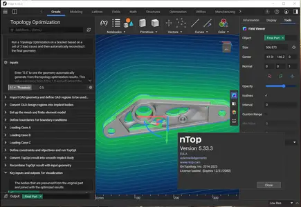
nTopology 5.33.3
nTopology 5.33.3 | 1.4 Gb
nTopology is pleased to announce the availability of nTopology 5.33.3. This release introduces new blocks for advanced surface modeling. We're excited to introduce three new sweep blocks: Conic Section Sweep, Conic Section Sweep by Tangent, and Cubic Bezier Section Sweep, giving you the control to create complex, blended surfaces. This release also includes the new Inline Custom Block feature for faster debugging and the Project Curve to Plane block, which enables the creation of 2D profiles from 3D geometry.
nTop 5.33 - What's New
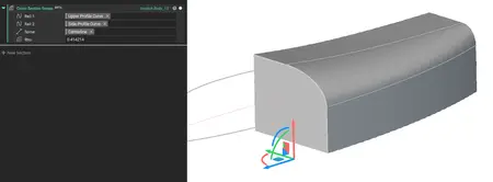
Conic Section Sweep
- The Conic Section Sweep block creates an implicit body by sweeping a conic implicit section along a spine curve between two rail curves.
- A spatially varying Rho field controls the shape of the conic section.
- This block is ideal for creating smooth surfaces with no inflections in workflows where the guide rails lie on perpendicular planes.
- Location: Beta > Modeling
- Inputs:
. Rail 1 (Curve): The first boundary curve that guides and constrains one side of the swept conic section as it travels along the spine.
. Rail 2 (Curve): The second boundary curve that guides and constrains the opposite side of the swept conic section as it travels along the spine.
. Spine (Line): A line that defines the sweep path and orientation for the conic section as it moves between the two rail curves.
. Rho (Scalar Field, Optional): A scalar field (0 to 1) that controls the conic shape factor at each point, where 0.5 produces a parabola, values less than 0.5 create elliptical sections, and values greater than 0.5 create hyperbolic sections.
- Output: Implicit Body
nTopology 5.33.3

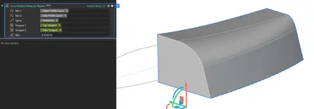
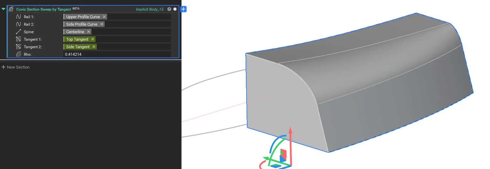
Conic Section Sweep by Tangent
- The Conic Section Sweep by Tangent block creates an implicit body by sweeping a conic implicit section along a spine curve between two rail curves.
- The tangent fields provide additional control over the curvature at the rails.
- Location: Beta > Modeling
- Inputs:
. Rail 1 (Curve): The first boundary curve that guides and constrains one side of the swept conic section as it travels along the spine.
. Rail 2 (Curve): The second boundary curve that guides and constrains the opposite side of the swept conic section as it travels along the spine.
. Spine (Line): A line that defines the sweep path and orientation for the conic section as it moves between the two rail curves.
. Tangent 1 (Vector Field, Optional): A vector field that specifies the direction of the Conic tangent handle at rail 1 for each point along the spine.
. Tangent 2 (Vector Field, Optional): A vector field that specifies the direction of the Conic tangent handle at rail 2 for each point along the spine.
. Rho (Scalar Field, Optional): A scalar field (0 to 1) that controls the conic shape factor at each point, where 0.5 produces a parabola, values less than 0.5 create elliptical sections, and values greater than 0.5 create hyperbolic sections.
- Output: Implicit Body
nTopology 5.33.3
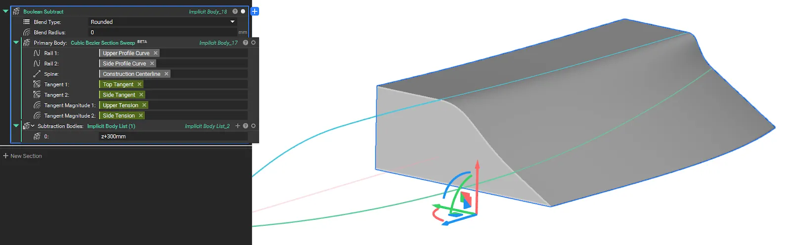
Cubic Bezier Section Sweep
- The Cubic Bezier Section Sweep block creates an implicit body by sweeping an implicit cubic Bézier section along a spine between two rail curves.
- The curve's shape is precisely controlled by spatially varying tangent vector fields and their magnitudes at each rail.
- The tangent vector fields define the direction of the Bézier control handles, while the magnitude fields control their lengths, offering detailed control over the surface's curvature where the guide rails lie on perpendicular planes.
- Location: Beta > Modeling
- Inputs:
. Rail 1 (Curve): The first boundary curve that guides and constrains one end of the swept cubic Bézier curve as it travels along the spine.
. Rail 2 (Curve): The second boundary curve that guides and constrains the opposite end of the swept cubic Bézier curve as it travels along the spine.
. Spine (Line): A line that defines the sweep path and orientation for the cubic Bézier curve as it moves between the two rail curves.
. Tangent 1 (Vector Field, Optional): A vector field that specifies the direction of the Bézier tangent handle at rail 1 for each point along the spine.
. Tangent 2 (Vector Field, Optional): A vector field that specifies the direction of the Bézier tangent handle at rail 2 for each point along the spine.
. Tangent Magnitude 1 (Scalar Field, Optional): A scalar field that controls the length of the tangent handle at rail 1, affecting the curve's pull toward that tangent direction. The tangent magnitude is relative to the in-plane distance between the rails.
. Tangent Magnitude 2 (Scalar Field, Optional): A scalar field that controls the length of the tangent handle at rail 2, affecting the curve's pull toward that tangent direction. The tangent magnitude is relative to the in-plane distance between the rails.
- Output: Implicit Body
nTopology 5.33.3
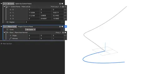
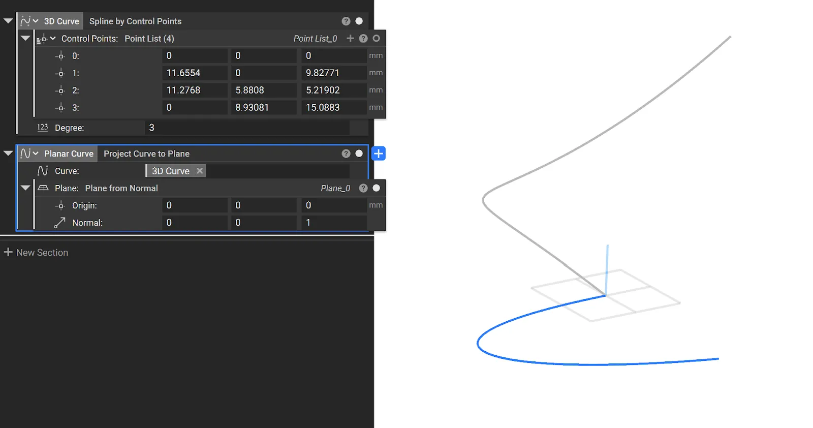
Project Curve to Plane
- The new Project Curve to Plane block that lets you project a 3D curve to a Plane, flattening it into a planar curve.
- Common uses:
. Implicit surfacing workflows
- Location: Modeling > Utilities
- Inputs:
. Curve: Curve to project.
. Plane: Plane to project to.
- Output: Curve
nTopology 5.33.3
Inline Custom Block
- You can now "unzip" a Custom Block directly within your nTop notebook. The Inline Custom Block feature replaces the Custom Block with its internal contents, allowing you to quickly inspect, modify, or debug its logic without having to open the block in a separate file. Values in the Custom Block's inputs prior to inlining will be linked directly to the downstream blocks previously inside the Custom Block..
- To use this feature, right-click on any Custom Block in your notebook and select Inline Custom Block from the context menu.
Usage Improvements
- You can now use the hotkey Ctrl+Shift+Left Arrow to collapse all sections in the notebook.
Block Updates
- The Pull Points to Plane block has been renamed to Project Points to Plane for clarity and consistency.
Bug Fixes
- We have fixed an issue where an extra /n (newline character) was incorrectly added to the description when creating input_template.json file using nTop Automate.
nTopology 5.33.3

nTopology introduced the concept of implicit modeling for mechanical design, which is an innovative, modern, and scalable way define parts and products. It has many benefits to end-users and companies, such as the elimination of model failures, speed of changes or iterations, and scalability to name a few. But implicit modeling enables so much more. In this informational session, we'll explore a topic that is redefining product development – field-driven design. In short, field-driven design is a way for design, analysis, and manufacturing teams to overlay information into one engineering model. This approach enables orders of magnitude increase in design iteration speed and greatly improves collaboration between teams.
How Field-Driven Design Allows Engineers to Design for Additive Manufacturing
Watch this information session where we'll define field-driven design, show examples of how it enables better knowledge sharing, and show how it promotes the development of more sophisticated, highly engineered products. You'll also better understand how nTopology is addressing today's engineering problems through its nTop Platform product.
nTopology was founded in 2015 to enable engineers and designers to create any geometry — no matter how complex — and meet the requirements of high-performance products.
Owner: nTopology
Product Name: nTopology
Version: 5.33.3
Supported Architectures: x64
Website Home Page : www.ntop.com
Languages Supported: english
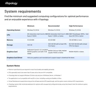
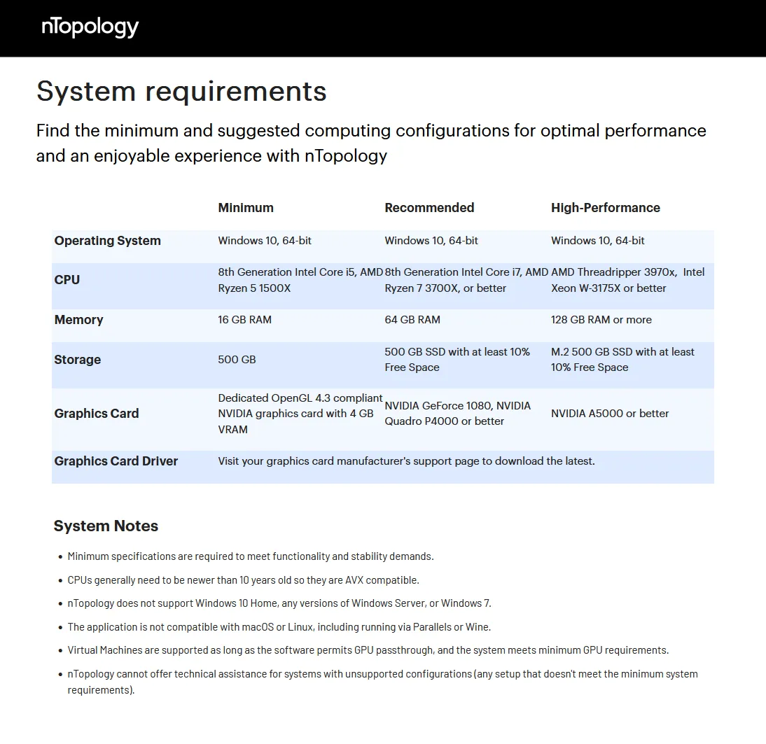
System Requirements: Windows *
Size: 1.4 Gb
nTopology 5.33.3
Please visit my blog
Added by 3% of the overall size of the archive of information for the restoration
No mirrors please

![nTopology 5.33.3]()
Added by 3% of the overall size of the archive of information for the restoration
No mirrors please
nTopology 5.33.3