
Cadence Design Systems Analysis Sigrity 2024.1 HF001 (24.10.001)
Cadence Design Systems Analysis Sigrity 2024.1 HF001 (24.10.001) | 11.9 Gb
Cadence Design Systems, Inc., a leader in global electronic design innovation, is pleased to announce the availability of Sigrity and Systems Analysis 2024.1 HF001 is a supplier of software for IC package physical design and for analyzing power integrity and signal integrity.
Sigrity and Systems Analysis (SIGRITY/SYSANLS) 2024.1 Release - Date: October 2024
Systems Analysis 2024.1
Clarity 3D Solver
- Clarity 3D Layout Structure Optimization Workflow: A new workflow, Clarity 3D Layout Structure Optimization Workflow, has been added to Clarity 3D Layout. This workflow integrates Allegro PCB Designer with Clarity 3D Layout for high-speed structure optimization.
- Component Geometry Model Editor: The new Clarity 3D Layout editor lets you set up ports, solder bumps/balls/extrusions, and two-terminal and multi-terminal circuits using a single GUI.
- Coaxial Open Port Option Added to Port Setup Wizard: The Coaxial Open Port option lets you create ports for each target net pin and reference net pin in Clarity 3D Layout. The nearby reference net pins are then used as a reference for each target net pin, reducing the number of ports needed. In addition, the ports of unused reference net pins are shorted to the ground.
- Parametric Import Option Added: Two new options, Parametric Import and Default Import, have been added to the Tools – Launch Clarity3DWorkbench menu. The Parametric Import option lets you import the design along with its parameters into Clarity 3D Workbench. The Default Import option lets you ignore the parameters when importing the design into Clarity 3D Workbench.
- Component Library Added to Generate 3D Components: Clarity 3D Workbench now includes a new component library that lets you use predefined 3D component templates or add existing 3D components to create 3D designs and simulation models.
- AI-Powered Content Search Capability: Clarity 3D Workbench and Clarity 3D Transient Solver now support an AI-powered capability for searching the content and displaying relevant information.
- Expression Parser to Handle Undefined Parameters: Clarity 3D Workbench and Clarity 3D Transient Solver support writing expressions or equations containing undefined parameters in the Property window to describe a simulation variable. The improved expression parser automatically detects any undefined parameter in an expression and prompts users to specify their values. This capability lets you define a model or a simulation variable as a function instead of specifying static values.
Clarity 3D Transient Solver
- Mesh Processing Improved to Simulate Large Use Cases: Clarity 3D Transient Solver leverages a new meshing algorithm that enhances overall mesh processing, specifically for large designs and use cases. The new algorithm dramatically improves the mesh quality, minimum mesh size, number of mesh key points, total mesh number, and memory usage.
- Advanced Material Processing Engine: The material processing capability has been enhanced to handle thin outer metal, which previously resulted in open and short issues in some designs. In addition, the material processing engine offers improved mode extraction for particular use cases, including waveguide and coaxial designs.
- Characteristic Impedance Calculation Improved: The solver engine now uses a new analytical calculation method to calculate the characteristic impedance of coaxial designs with improved accuracy.
Celsius Studio
- Celsius Interchange Model Introduced: Celsius Studio now supports Celsius Interchange Model generation, which is a 3D model derived from detailed physical designs for multi-physics and multi-scale analysis. This Celsius Interchange Model file (.cim) serves as a design information carrier across Celsius Studio tools, enabling a variety of simulation and analysis tasks.
- Celsius 3DIC Thermal Workflow Improvements: The Thermal Simulation workflows in Celsius 3DIC have been significantly enhanced. Key improvements include:
. Advanced Power Setup with Transient Power Function and Multi Mode options
. Enhanced GUI for the Mesh Control and Simulation Control tabs
. Improved meshing capabilities
. Celsius Interchange Model (.cim) generation
. Material library support for block and connections
. Import of Heat Transfer Coefficients (HTCs) from a CFD file
. Bump creation through the Bump Array Wizard
. Layer Stackup CSV file generation
- Celsius 3DIC Warpage and Stress Workflow Enhancements: The Warpage and Stress workflow in Celsius 3DIC has undergone significant improvements, such as:
. Improved multi-stage warpage simulation flow for 3DIC packaging process
. Enhanced GUI for the Mesh Control, Simulation Control, and Stress Boundary Conditions tabs
. Support for large deformations and temperature profiles
. Bump creation through the Bump Array Wizard
. New constraint types
. Enhanced meshing capabilities
- Geometric Nonlinearity Support in Warpage and Stress Analysis: Large deformation analysis is now supported in warpage and stress studies. This study uses the Total Lagrangian approach to model geometric nonlinearities in simulation, which allows accurate prediction of final deformations.
- Thermal Network Extraction and Simulation: In the solid extraction flow in Celsius 3D Workbench, you can now import area-based power map files to create terminals. For designs with multiple blocks, this capability allows automatic terminal creation, eliminating the need to manually create and set up 2D sheets individually. Additionally, thermal throttling feature is now supported in Celsius Thermal Network. This makes it ideal for preliminary analyses or when a quick estimation is required. It runs significantly faster than 3D models, allowing for quicker iterations and more efficient decision-making.
Sigrity 2024.1
Layout Workbench
- Improved Graphical User Interface: A new option, Use Improved User Interface, has been added in the Themes page of the Options dialog box in the Layout Workbench GUI. In the new GUI, the toolbar icons and menu options have been enhanced and rearranged.
Broadband SPICE
- Python Script Integration with Command Line for Simulation Tasks: Broadband SPICE lets you run Python scripts directly from the command line for performing simulation and analysis. The new -py and *.py options make it easier to integrate Python scripts with the command-line operations. This update streamlines the process of automating and customizing simulations from the command line, which makes your simulation tasks faster and easier.
Celsius PowerDC
- Block Power Assignment (BPA) File Format Support: PowerDC now supports the BPA file format. Similar to the Pin Location (PLOC) file, the BPA file is a current assignment file that defines the total current of a power grid cell, which is then equally distributed across the power pins within the cell. This provides better control over the power distribution.
- Ability to Run Multiple IR Drop Cases Sequentially: You can now select multiple result sinks from the Current-Limited IR Drop flow and run IR Drop analysis for them sequentially. PowerDC automatically runs the simulations in sequence after you select multiple result sinks. This saves time by automating the process.
- Enhanced Support for Mixed Conversion Devices: PowerDC now supports mixing different conversion devices, such as switching regulators and linear regulators within a single DC-DC/LDO instance. This enhancement offers added flexibility by letting you configure each instance in your design according to your specific needs.
PowerSI
- Monte Carlo Method Added: A new option, Monte Carlo Method, has been added in the Optimality dialog box. This option lets you create multiple random samples to depict variations in the input parameters and assess the output.
- Channel Check Optimization Added: The S-Parameter Assessment workflow in PowerSI now supports Channel Check Optimization. It uses the AI-driven Multidisciplinary Analysis and Optimization (MDAO) technology that lets you optimize your design quickly and efficiently with no accuracy loss.
SPEEDEM
- Multi-threaded Matrix Solver Support Added: The Enable Multi-threaded Matrix Solver check box has been added that lets you accelerate the simulation speed for high-performance computing. This check box provides two options, Automatic and Always, to include the -lhpc4 or -lhpc5 parameter, respectively, in the SPEEDEM Simulator (SPDSIM) before running the simulation.
XtractIM
- Options to Skip or Calculate Special DC-R Simulation Results: The Skip DC_R of Each Path and Only DC_R of Each Path options have been added to the Setup menu.
. Skip DC_R of Each Path: This option lets you skip the calculation of the DC-R result during the simulation. Other results, such as SPICE T-model, RL_C of Each Path, Coupling of Each Path, etc., are still calculated.
. Only DC_R of Each Path: This option lets you calculate the DC-R result only during the simulation. Other results, such as SPICE T-model, RL_C of Each Path, Coupling of Each Path, etc., are not calculated.
- Color Assignment for Pin Matching: The MCP Auto Connection window includes the Display Color Editor, which lets you assign a color for pin matching. It helps you easily identify the matching pins in the left and right sections of the MCP Auto Connection window.
- Ability to Save Simulations Individually: The Save each simulation individually check box has been added to the Tools - Options - Edit Options - Simulation (Basic) - General form. Select this check box and run the simulation to generate a simulation results folder containing files and logs with a timestamp for each simulation.
- Reuse of SPD File Settings: The XtractIM setup check box lets you import an existing package setup to reuse the configurations and settings from one .spd file to another.
Documentation Enhancements
Cloud-Based Help System Upgraded
- The cloud-based help system, Doc Assistant, has been upgraded to version 24.10, which contains several new features and enhancements over the previous 2.03 version.
2999198 3D_FDTD The Clarity 3D Transient Solver GUI always opens in the Clarity FEM flow
2999213 3D_FDTD Clarity 3D Transient Solver exits unexpectedly when checking the near-field results
3033724 ASI_PI SPDGEN translation causes PowerDC to generate an error due to touching conductors
2934508 CELSIUS Via with oblong drill appears as a solid shape in Celsius 3D
2992682 CELSIUS The terminal name from Celsius EC Solver does not match with Celsius 2D
3011982 CELSIUS Celsius 2D fails to run stress simulation
3017579 CELSIUS The Z coordinate and height direction are wrong in Celsius 3D Workbench component definition
3030963 CELSIUS DC block shows incorrect short in Celsius 3D
2805002 CLARITY The D-Sarkar model displays only one point in Clarity 3D Workbench
2960691 CLARITY Help buttons in Solver>Excitations>Wizard in Clarity 3D Workbench are not working
2960714 CLARITY Clarity 3D Layout multiple structure design does not load into Clarity 3D Workbench when launched
2966291 CLARITY Add support for through-hole translation in pad in Clarity 3D Workbench
2971270 CLARITY Layered IBC two-sided shell element needs a normal top vector and a reverse button support
2974829 CLARITY The circuit port moved from its original position when imported using 'Import Component' in Clarity 3D Workbench
2976571 CLARITY Clarity 3D Layout simulation stops responding at initial mesh
2976879 CLARITY 'Fmax' changes with 'Sampling Type' after selecting a different frequency unit
2979622 CLARITY 'Clarity 3D Layout Multiple Structure Simulation' workflow fails to run the simulation
2979925 CLARITY Clarity 3D Layout simulation gets stuck at LMesh stage and does not proceed further
2983275 CLARITY Calling PowerDC from Clarity 3D Layout fails if coaxial wave ports are used
2984313 CLARITY Clarity 3D Layout cannot complete frequency sweeping on Windows
2985480 CLARITY Simulation fails to run in Clarity 3D Workbench
2990129 CLARITY Clarity 3D Layout fails at AMR stage with mixed ports including wave ports
2996444 CLARITY The simulation log shows that the multi-terminal circuit model failed to load even though the model is loaded
2998006 CLARITY Ports created using the 'Ports by Edge Projection' option show different orientation on discretized cylindrical bump
2998901 CLARITY The calculation at low frequency points is inaccurate in the case of wave ports
2999241 CLARITY Frequency sweep does not converge in Clarity 3D Layout
3009058 CLARITY The 'Clarity 3D Layout Full-Wave Spatial' mode simulation fails for wave port cases
3009440 CLARITY The 'Clarity 3D Layout Full-Wave Spatial' mode simulation fails at volume mesh stage
3009831 CLARITY Cannot disable one of the structures in the 3D field visualization in Clarity 3D Layout
3010413 CLARITY The Port field does not show fields for more than one port when using multi-ports in Clarity 3D Layout
3010714 CLARITY Clarity AMR Performance Issue, Phase3 Slowness
3010725 CLARITY Windows HPC Old & New Atlas Python Compatibility & Consolidation Issue
3012595 CLARITY Clarity 3D Layout simulation fails with XMesh but runs fine with DMesh
3022890 CLARITY Layer impedance test case failed with DMesh in Clarity
3023757 CLARITY Clarity 3D Layout simulation results are wrong with the given test case
3028109 CLARITY Material unexpectedly changed to a different one in Clarity 3D Workbench
3031275 CLARITY Clarity 3D Workbench fails at DC simulation and no log file is generated
3031352 CLARITY Leaving VEM_MULTIPLE_MODEL_REFS undefined inverts bondwires
3036087 CLARITY Translation issue occurs in Clarity 3D Workbench with 'Extract Geometry for Standalone Circular Objects' option selected
3038522 CLARITY An error occurs in Clarity 3D Workbench while generating the surface mesh
3044864 CLARITY A connector design has mesh issues, port issues, and shows open results
2824091 OPTIMIZEPI The OptimizePI simulation for rigid-flex PCB fails in Linux but succeeds in Windows
3031683 OPTIMIZEPI There is no difference in PKGBGA impedance results with or without DIE .subckt model in OptimizePI
2978800 POWERDC Sink with only positive pins in PowerTree is not created in PowerDC
2979167 POWERDC PowerDC generates undesirable E/T Co-sim IR-drop results
2980311 POWERDC The reference voltage drop result of SinkPin.csv in PowerDC Multi-Board simulation is not consistent
2986864 POWERDC The PowerDC Multi-Board DC Block diagram report has problems
2988380 POWERDC Sense pin setup issue for PowerDC Multi-board
2988437 POWERDC PowerDC setup done in PowerTree Multi-Board is not applied in PowerDC
2994440 POWERDC Sense pin defined in PowerTree Multi-Board is not applied in PowerDC
3006635 POWERDC Thermal simulation option 'Use enhanced heat transfer coefficient model' is not working as expected in Celsius PowerDC
3007582 POWERDC The P/F Mode option is not displayed in PowerDC when creating a sink manually
3010572 POWERDC The DC-DC component created in pin-based PowerTree is different from net-based PowerTree
3017955 POWERDC Inactivating components does not work properly in PowerDC
3031467 POWERDC PowerDC resistance measurement generates unexpected results
2989286 POWERSI How to calculate INT_XTK in 'S-Parameter Assessment' flow
2994387 POWERSI PowerSI exits unexpectedly when IPC and DP solver are on
2997745 POWERSI PowerSI does not generate DC fitting and DC results after simulation
3010416 POWERSI PowerSI simulation fails with trench via environment variables enabled
3025846 POWERSI PowerSI simulation gets stuck and does not proceed further
3030054 POWERSI PowerSI simulation does not generate any result
2934573 SIGRITY_SUITE An issue occurs when generating Down Vertical ports in Clarity 3D Layout
2936878 SIGRITY_SUITE Model assignment issue occurs in PowerDC when PowerTree is linked to AMM
2947518 SIGRITY_SUITE When running Tcl automation, OptimizePI exits unexpectedly
2949615 SIGRITY_SUITE *.ammx cannot be model assigned with other *.brd
2952076 SIGRITY_SUITE The 'Show Y-axis in log scale' option does not change the value of curve
2957696 SIGRITY_SUITE Clarity 3D Layout Structure Optimization simulation fails
2965352 SIGRITY_SUITE Pads not vertically aligned and create open circuits when launching Clarity 3D Workbench from Clarity 3D Layout SO flow
2976980 SIGRITY_SUITE Shape is missing after processing merged package and PCB
2978240 SIGRITY_SUITE The Python command 'get_conductivity()' gets the wrong conductivity value
2988547 SIGRITY_SUITE The result of PSXT is smaller than the original crosstalk
2990087 SIGRITY_SUITE The trace reference layers are incorrect in Trace Editor due to translation issue
2991070 SIGRITY_SUITE PowerDC fails to run the Clarity DC point simulation if the layout has magnetic materials
2994432 SIGRITY_SUITE Clarity 3D Layout stops responding when cutting the design boundary by enabled nets
2995251 SIGRITY_SUITE PowerTree Multi-Board simulation exits unexpectedly when trying to update the netlist from a block
2995456 SIGRITY_SUITE The net display of node is not updated
3001294 SIGRITY_SUITE Self term display issue occurs with 'Clarity 3D Layout Inductance Extraction' workflow
3005490 SIGRITY_SUITE Transform stackup does not work properly in Sigrity 2024.0
3007629 SIGRITY_SUITE 'Copy to ClipBoard' is copying only the design outline
3010417 SIGRITY_SUITE Cannot zoom in to a curve of Group Delay in BnpViewer
3010419 SIGRITY_SUITE Multiple area ports are created between the same objects in Clarity 3D Layout
3010432 SIGRITY_SUITE The width of area ports created in Clarity 3D Layout is thin
3010500 SIGRITY_SUITE Area ports are not created in certain regions in Clarity 3D Layout
3010674 SIGRITY_SUITE The number of wave ports is incorrect after merging PKG and PCB in Clarity 3D Layout
3010972 SIGRITY_SUITE Wave ports cannot be created successfully or created with the wrong net in Clarity 3D Layout
3011355 SIGRITY_SUITE Issue in header information generated in Clarity 3D Layout
3025053 SIGRITY_SUITE Creating vertical ports from components creates voids on power nets
3029162 SIGRITY_SUITE The 'Clarity 3D Layout Structure Optimization' workflow cannot change the solution frequency and sweep frequency range
3035100 SIGRITY_SUITE Clarity 3D Layout simulation generates an error with Sigrity 2024.0 HF1 but works fine with Sigrity 2023.1 HF4
3036678 SIGRITY_SUITE The Resistor component is not enabled automatically and its pin diameter is too large
3045404 SIGRITY_SUITE The new port group name created using the 'sigrity::group port' Tcl command is incorrect
3048043 SIGRITY_SUITE Powersum Xtalk shows unexpected results
3051966 SIGRITY_SUITE Clarity 3D Layout becomes unresponsive at initial mesh
3007690 SPEED2000 Error message output for IBIS Golden Parser problem
3026452 SPEED2000 Extracting S-parameters from a SPICE file generates the message 'Stopped running the S Parameter extraction'
3043403 SPEED2000 IDA Impedance ERC fails without generating an error message
2923265 TRANSLATOR Stubs are missing when running translation using the 'Remove non-functional pads' option
2958114 TRANSLATOR Circles are not displayed correctly when importing a DXF file
2961836 TRANSLATOR ODB++ translation creates an additional layer and wrong component placement
2963088 TRANSLATOR Gds2Spd layer is not translated if multiple GDS numbers are set to the same layer name
2965185 TRANSLATOR Gds2Spd layers 'bulksi' and 'pec' should be independent and should not depend on 'average_above' and 'average_below'
2965195 TRANSLATOR The dielectric layer above the top layer is not translated properly using Gds2Spd
2965311 TRANSLATOR Gds2Spd metal layer is ignored unless the map layer is reloaded
2974395 TRANSLATOR Translation problem occurs with the W component
2979566 TRANSLATOR BRD2SPD translation consumes all available RAM and causes the translator to exit unexpectedly
2987794 TRANSLATOR BRD2SPD translation causes the translator to exit unexpectedly in Sigrity 2024.0
2992784 TRANSLATOR Gds2Spd translation fails when using the same tech/map/iRCX file with different GDS
3001882 TRANSLATOR Wrong model number addition after translation of ODB++ file
3009868 TRANSLATOR Importing a GDS file creates gaps in shapes during translation to SPD
3012769 TRANSLATOR The metal layers in the map and tech file do not get translated using Gds2Spd
3034604 TRANSLATOR Shape translation problem occurs with the ICT file in Gds2Spd
3036722 TRANSLATOR Clarity 3D Layout exits unexpectedly when loading a .mcm file
3041040 TRANSLATOR Clarity 3D Layout/PowerSI/Layout Workbench exits unexpectedly when trying to import an ODB++ (.tgz) file
3042650 TRANSLATOR SPDGEN translation drops all degassing holes from the interposer design
2988640 XCITEPI XcitePI exits unexpectedly during PDN extraction
3008926 XTRACTIM XtractIM generates an error if a net contains DIE and CAP without BGA; reference pin(s) has partial inductance
Sigrity and Systems Analysis (SIGRITY/SYSANLS) 2024.1 HF001 Release - Date: 12-06-2024
3041109 CELSIUS Celsius3D current density display not scaled with Z
3047281 CLARITY The boundary condition update does not reflect in the 'BoundaryConditions' tree structure on the Project panel
3067099 CLARITY Frequency-dependent equation is wrong in the control file
3069985 CLARITY Metallic objects in Field plot are not accessible
3072830 CLARITY Numeric values of the fields cannot be exported in Clarity 3D Workbench
3077206 CLARITY Step file cannot be opened in Clarity 3D Workbench in the Sigrity 2024.1 release
3080112 OPTIMALITY [Monte-Carlo Flow] Parameter history does not match when Tcl command is used
3048097 OPTIMIZEPI Let 'Rev R-L' target Z drive the decap optimization in OptimizePI
3051631 OPTIMIZEPI OptimizePI exits unexpectedly after starting optimization (best scheme vs area)
3052391 POWERDC PowerDC multi-board IR drop simulation displays incorrect reference VRM and voltage
3057994 POWERDC PowerDC exits unexpectedly if SINK/VRM is not defined properly
2977413 SIGRITY_SUITE The Clarity grouped port setup is lost if the layout is saved in PowerDC
3006945 SIGRITY_SUITE Clarity 3D Layout Multiple Structure Simulation fails on a design that runs successfully in Clarity 3D Workbench
3073152 SIGRITY_SUITE 'Polygon simplification' value changes automatically in 'Intelligent-Multi-Block Extraction with HPC- Full-Wave IC' flow
3073393 SIGRITY_SUITE 'Enable' option is ignored and blocks are randomly selected in Intelligent-Multi-Block Extraction with HPC- Full Wave IC
3070005 TRANSLATOR Clarity 3D Layout cannot open an mcm file and generates an error
Cadence Sigrity provides a rich set of gigabit signal and power network analysis technologies, including a unique power-aware signal integrity analysis capability for system, printed circuit board (PCB), and IC package designs. The combination of Sigrity analysis technologies with Cadence Allegro and OrCAD design tools will provide a comprehensive front-to-back integrated flow to enable system and semiconductor companies to deliver high-performance devices employing gigabit interface protocols such as DDR and PCI Express. The integrated solution will particularly benefit customers delivering electronic systems in high-growth markets such as mobile multimedia devices and cloud computing infrastructure.
Systems Analysis products complement Sigrity tools and are focused on complete systems. Thermal, EMI, RF, and extraction simulations include design data beyond ECAD and often include MCAD components such as antennas, cables, connectors and enclosures.
Cadence Sigrity: How to Avoid Power Delivery Problems in your PCBs
Ensure uniform current density in your design and put a stop to the additional time and money spent on troubleshooting hard to find power delivery network issues in the lab with Allegro In-Design Analysis powered by Sigrity.
Cadence is a pivotal leader in electronic systems design, building upon more than 30 years of computational software expertise. The company applies its underlying Intelligent System Design strategy to deliver software, hardware and IP that turn design concepts into reality. Cadence customers are the world’s most innovative companies, delivering extraordinary electronic products from chips to boards to complete systems for the most dynamic market applications, including hyperscale computing, 5G communications, automotive, mobile, aerospace, consumer, industrial and healthcare. For eight years in a row, Fortune magazine has named Cadence one of the 100 Best Companies to Work.
Owner: Cadence Design Systems
Product Name: Sigrity and Systems Analysis
Version: 2024.1 HF001 (24.10.001)
Supported Architectures: x64
Website Home Page : www.cadence.com
Languages Supported: english
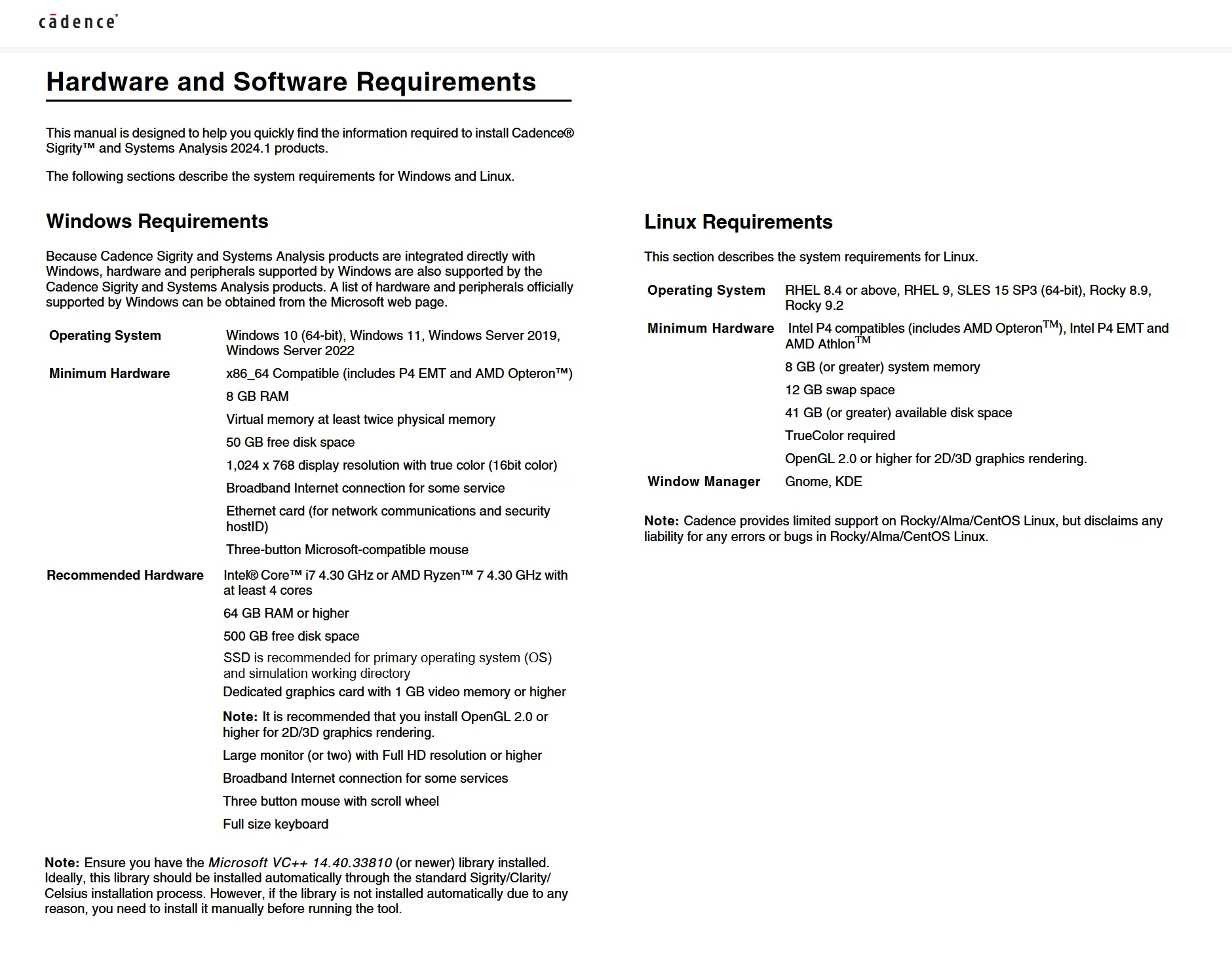
System Requirements: Windows *
Size: 11.9 Gb
Cadence Design Systems Analysis Sigrity 2024.1 HF001 (24.10.001)
Please visit my blog
Added by 3% of the overall size of the archive of information for the restoration
No mirrors please

![Cadence Design Systems Analysis Sigrity 2024.1 HF001 (24.10.001)]()
Added by 3% of the overall size of the archive of information for the restoration
No mirrors please
Cadence Design Systems Analysis Sigrity 2024.1 HF001 (24.10.001)