

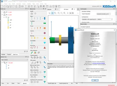
KISSsoft 2025 SP1
KISSsoft 2025 SP1 | 273.9 mb
Languages Supported: Español, 中文, Deutsch, English, Français,
Italiano, 日本語, Português, Русский
Languages Supported: Español, 中文, Deutsch, English, Français,
Italiano, 日本語, Português, Русский
KISSsoft, a part of multi-national Gleason Corporation, is pleased to announce the availability of KISSsoft 2025 SP1 is a modular calculation system for the design, optimization and analysis of machine elements.
What's new in KISSsoft Release 2025 SP1
General
SP 1 - Gear facewidth used in the 3D viewer
Correction in the gear facewidth used in the 3D viewer, for the case of multi-mesh gears
SP 1 - Influence of operating temperature on safety added
The input value of the operating temperature had no influence on safety endurance and yield limit.
SP 1 - Save button for data representation tables
The save button has been added to all data representation tables.
SP 1 - Saving own material data for snap rings
User inputted material data is now saved correctly.
SP 1 - Updating σFlim data for Delrin 100
The σFlim data for Delrin 100 was updated with the values from Delrin 100 CPE as the original data was measured with inadequate gear temperature control.
System Module General
SP 1 - Automatic zooming in sketcher improved
The automatic zooming for the sketcher in case of a floating tab has been improved.
SP 1 - DEL key activated for group view
The group view allows deleting via the DEL key.
SP 1 - Elements in 3D viewer
Solves a case where 3D elements would disappear from the 3D viewer, in the shaft editing mode.
SP 1 - Planet bearings in the 3D viewer
Improvement in the visibility of planet bearings in the 3D viewer.
SP 1 - Power loss table size
The size of the power loss definition table has been improved.
Sketcher
SP 1 - Annotations visibility improved
The annotations in the sketcher can be switched on and off individually.
Housing Deformation
SP 1 - Housing deformation calculation
Improvement in the update of shaft calculations in the iterations of housing deformation.
Eigenfrequencies
SP 1 - UI parameters and graphics property list in the Campbell diagram
The Campbell diagram now supports independent control of UI parameters and graphics property lists. Users can simultaneously adjust settings, such as "Number of calculation steps," in the UI while modifying "Number of resonance curves" in the property list, providing greater flexibility in diagram configuration.
Forced Response Gears
SP 1 - 3D deformation in the forced response
3D deformation in the forced response analysis is modified to correctly consider the effect of forces at all excitation frequencies.
SP 1 - Calculation of bearing forces of the carrier shaft in forced response analysis
Calculation of bearing forces of the carrier shaft in forced response analysis for a special case did not result to any output.
SP 1 - Modification of the effect of shaft damping in the dynamic analysis
The effect of shaft damping in tension, axial, and bending directions is modified for the special case when only the torsional DOF is required. For this case, only the torsional damping (and not axial or bending damping) exposes the effect to e.g. the dynamic factor.
SP 1 - Postprocessing of the gear boxes with idle gear pair
In the forced response analysis of gearboxes with idle gear pair, the idle gear pair should not lead to any non-calculated result for active pairs.
Forced Response Shafts
SP 1 - Curve saving in the forced response analysis in the shaft module
Activation of saving the curves in the forced response analysis graphic in the shaft module, when the option “Reference position” is selected.
Gears
SP 1 - Diametral pitch with imperial units
When switching from metric to imperial units, KISSsoft is also switching to input of normal diametral pitch, and vice versa. In the calculation settings you can overwrite the setting.
SP 1 - Radio buttons for tooth thickness allowance selection
Radio buttons for tooth thickness allowance selection are working again.
SP 1 - Setting the Driving gear for beveloid, face, bevel, worm, and crossed helical gears
It is again possible to set the "Driving gear" for beveloid, face, bevel, worm, and crossed helical gears.
Cylindrical Gears Rating
SP 1 - Woehler curve graphics
In some cases, when SN curves were defined in a DAT file, the curves in the graphic were not displayed correctly. The calculation results were not affected.
Cylindrical Gears Geometry
SP 1 - Backlash calculation with actual tooth form
Flank line modifications for the first gear in a gear pair are now properly considered in the backlash calculation with actual tooth form.
SP 1 - Calculation of dFf and dFa using pinion type cutter
The accuracy of the calculation of dFf and dFa using pinion type cutter has been improved.
SP 1 - Conversion dialogue for haP0 and hfP0
Conversion dialogue for haP0 and hfP0 was not working properly for hobbing cutter and pinion type cutter. Additionally, also the calculation of the tip diameter da is now correct when using a topping pinion type cutter.
SP 1 - Improvements on hobbing process
The algorithm for finding a time optimized hob improved, e.g. it will now adapt the step size for the outer diameter on the size of the diameter.
SP 1 - Pre-machining manufacturing profile shift in tab tooth form
Pre-machining manufacturing profile shift (max) is now calculated correctly for several tooth form operations in tab tooth form.
Bevel Gears
SP 1 - Export of EPG values to GEMS
The export of EPG values to GEMS is now working again for the nominal calculation.
SP 1 - Warning message for factor ZKP
Warning message for factor ZKP is now shown correctly in case of user defined value.
Crossed Helical Gears
SP 1 - Meshing power loss calculation
Meshing power loss calculations are refined when the reference gear is not identical to the driving gear.
Shafts
SP 1 - 3D animation in the shaft calculation
Improvement in the 3D animation in the shaft calculation, when opened from the system module.
SP 1 - Accessing shaft elements from script or COM interface
Various parameters of shaft elements can now be accessed and modified from script or COM interface by using Meta functions SetElementData(…) and GetElementData(…) when using shaft module, or by using functions SetShaftCalcElementData(…) and GetShaftCalcElementData(…) when using system module.
SP 1 - Free cross section input
Free cross section input for tip and root diameter is fixed.
SP 1 - Gear facewidth used in the results graphic
Correction in the gear facewidth used in the results graphics, for the case of multi-mesh gears.
SP 1 - Gear inner diameter
When gear data is read from the gear calculation file, inner diameter of the gear (outer diameter in case of internal gear) is now also read from the file.
SP 1 - General support/joint with option Eccentric thrust bearing
Stiffness, clearance and damping inputs are now shown also for general support or joint with Own input and with enabled option Eccentric thrust bearing.
SP 1 - Renaming of sub elements added in shaft tree view
Sub elements can now directly be renamed in the shaft tree view.
SP 1 - Shaft 3D viewer
Speed arrows are shown in the 3D view of shafts in the shaft calculation.
SP 1 - Shaft strength calculation with load spectra and small load sum
When running shaft strength calculation for load spectrum with small load sum, variable amplitude factor KBK is set to 1 now. Until now it was set to 0 which resulted in zero fatigue safety factors for some cases.
SP 1 - Shaft support stiffness flag
Flag for entering stiffness of the support was always turned off when switched from the support element to some other element and then back to the support.
Bearings
SP 1 - Color bar legend in 3D graphics
Color bar legend in 3D graphics has again the correct color distribution.
SP 1 - Pressure curve graphics for roller bearings
Roller bearing pressure curve graphics now shows different colors and line styles for each roller.
SP 1 - Rolling bearings with zero speed in load spectrum calculation
When using load spectrum calculation, the speed of rolling bearings which don't rotate at all, is now set to 0.0001 rpm. Until now this value was assigned to speed ratio, not to speed itself. This has effect on rolling bearing rating life calculation if the rotating speed in a bin is set to zero and nominal rotating speed is high.
SP 1 - Sizing clearance with oil outlet temperature
Sizing clearance with oil outlet temperature is improved for different calculation methods.
Shaft-Hub Connections
SP 1 - Corner distance calculation for non sharp-edged abutment
The corner distance h is calculated without the influence of the corner distance g, when the abutment is not sharp-edged.
SP 1 - Diametral measurement over pins (actual)
The values for the diametral measurement over pins (actual) are again correct in the calculation.
SP 1 - Groove load capacity FN' with influence of factor p and relation t'/t
Groove load capacity FN' is calculated with influence of factor p and relation t'/t, according to Seeger catalogue.
Bolts
SP 1 - Mounting force and tightening torque with operating temperature
When defining utilization for mounting with operating temperatures, in some cases the utilization was related to the operating temperature, which could affect FM and MA. Now the utilization input relates to the mounting temperature.
SP 1 - Tolerance 7H and 8H for D1max
The tolerances 7H and 8H for D1max had the wrong order in the database. The tolerances are now correct.
FEM Calculations
SP 1 - 2D FEM root stress results
The presentation of results for 2D root stress FEM simulations is improved. This can lead to differences in results compared to previous versions.
SP 1 - 3D FEM root stress robustness
The overall robustness of the root stress 3D FEM module has been improved. This can lead to differences in results compared to previous versions.
SP 1 - 3D Root Stress FEM
The application of contact forces in the 3D root stress model has been improved. This increases the accuracy of the simulation.
SP 1 - 3D Root Stress FEM Graphics Improvement
The visualization of contact lines for 3D FEM models is improved.
SP 1 - 3D root stress FEM mesh
The mesher for 3D FEM models is improved. This enhances the reliability of the simulations.
Scripting
SP 1 - Array literals
Variables can now be initialized from array literals, e.g., number[][] array = [ [0, 1, 2], [2, 3, 4]].
SP 1 - Update of floating skript editor
Floating skript editor does update automatically.
STEP-Interface
SP 1 - Step export of shaft system with worm gear
Improvement in the orientation of a worm gear, contained in the step export of a shaft system.
CAD-Interfaces
SP 1 - Interface to Autodesk Inventor 2026
Interface to Autodesk Inventor 2026 added.
SP 1 - Rack generation in SolidWorks
The SolidWorks interface for racks is again working correctly.
SP 1 - Right handed helical gears generation in NX
Right handed helical gears are now fully generated in NX Interfaces for Data Exchange
SP 1 - Exporting/importing modifications in GDE format
The following modifications are now supported in the GDE export/import: Linear tip and root relief, Roll-length centered profile crowning, Flank line crowning, Twist, Pressure angle modification (arc minutes), Helix angle modification (arc minutes) and Linear end relief. Versions 3.1, 3.2 and 3.3 are affected.
KISSsoft 2025 SP1

KISSsoft is a modular calculation program for the design, optimization and verification of machine elements according to international standards. The individually customized software packages for a wide variety of applications guarantee tailor made solutions and the integration to all common CAD software complete the product.
KISSsoft Release 2025 | Improved design efficiency | New features
This webinar focuses on the new features of KISSsoft Release 2025 that introduce innovations for improved results visualization, improving design efficiency, and productivity. Learn how the enhancements in the KISSsoft Release 2025 offer a completed solution from manufacturing functions to bearing ratings methods.
KISSsoft is part of multi-national Gleason Corporation, as a wholly owned subsidiary. KISSsoft AG directly serves various industries and customers globally. The most powerful source of ideas are our customers: Suggestions and recommendations from innovative companies throughout the world have all contributed to the further development of our software, ensuring that KISSsoft, KISSsys as well as KISSdesign are always at the forefront of technology.
Owner: KISSsoft
Product Name: KISSsoft
Version: 2025 SP1 Update
Supported Architectures: x64
Website Home Page : www.kisssoft.com
Languages Supported: multilanguage
System Requirements: Windows *
Software Prerequisites: pre-nstalled KISSsoft 2025 SP0
Size: 273.9 mb

KISSsoft 2025 SP1

KISSsoft 2025 SP0
Please visit my blog
Added by 3% of the overall size of the archive of information for the restoration
No mirrors please

![KISSsoft 2025 SP1]()
Please visit my blog
Added by 3% of the overall size of the archive of information for the restoration
No mirrors please
KISSsoft 2025 SP1