
Siemens Solid Edge Electrical Design 2020 SP2002

Siemens Solid Edge Electrical Design 2020 SP2002 | 2.7 Gb
Languages: 中文 (Simplified), 中文 (Traditional), Čeština, English, Français, Deutsch,
Magyar, Italiano, 日本語, 한국어, Polski, Português-Brazilian, Русский, Español
Languages: 中文 (Simplified), 中文 (Traditional), Čeština, English, Français, Deutsch,
Magyar, Italiano, 日本語, 한국어, Polski, Português-Brazilian, Русский, Español
Siemens Digital Industries Software announces the 2021 SP2002 version of Solid Edge Wiring and Harness Design software. These mod-ules enable engineers to collaborate seamlessly between electrical and 3D mechanical design.
Solid Edge Wiring & Harness Design 2020 SP2002.77 Release Notes - Date: February 2020
New Features
Synchronize data to SEWHD (Create Design from Teamcenter Item)
With this new functionality, user can now synchronize data to SEWHD from Teamcenter. In order to support this, four new buttons are added in embedded Active Workspace Ribbon.
Using Associate button, user can link SEWHD Project/Design to Teamcenter Item Revision through PDM_ID & PDM_REV for selected item in Active Workspace Client (AWC).
Using Update button, user can update all the user defined properties from Teamcenter as per mapping in seelectricalTC.Properties.
Associate & Update actions can be performed on one or multiple designs.
Using Find button, user can later find all the associated Design(s) in the current Project.
Add button in AWC will help user to add new design of all design types in SEWHD based on seelectricalTC.Properties. If association for selected item already exists then user will be able to create a new design.
Single Sign On for Teamcenter based on TcSS
In case the Teamcenter environment is setup to use Teamcenter Security Service (TcSS) for Single Sign On for all applications, the Capital integration can now be configured to directly reuse this approach when connecting to Teamcenter. In this case there is no need to specify username and password in the Configure dialog on Capital side.
Quickly add Backshells and Terminations in SE-E Design
The current process of adding Backshell and Backshell Terminations in SE-E Design involves a number of clicks and entries in a dialog box. Also, it does not show name of next Backshell and Backshell terminations. This feature enables users to easily add a Backshell and Terminations onto their connectors, displaying their names.
To add a Backshell Termination, right-click on the connector and select the Add/Edit Backshell menu option. In the Backshell dialog, you will be presented with the termination name. Select it and click the OK button.
Alternatively, you can also add Backshell Terminations using one of the following methods:
- Press Space Bar and enter Add Backshell Termination.
- Right-click and select Add Backshell Termination from the context menu.
- Re-select the connector for which you are creating Backshell Terminations and press CTRL + B.
Pressing CTRL + B is the quickest method of adding multiple instances of Backshell Terminations. Composite/Default naming rules will be applied to the new termination. Once added the name can be changed
The following Service Requests are resolved in this Service Pack.
SB3396564961 SB3396578751 Analysis Unable to open any analysis tool when in traditional Chinese locale and leads to error
SB3426978851 Bridges DSI file should not include all the Project option codes when no options are assigned to the design
SB3326932141 Framework Printing to PDF with invalid, missing or corrupted images in a diagram displays a blank PDF or crashes application
SB3230843131 Framework Selection inconsistency issue – Values change from mm to pin grid after multiple files selected
SB3410023441 Framework Printing to PDF with invalid, missing or corrupted images in a diagram displays a blank PDF or crashes application
SB3291679443 SB3314536231 Framework UI Border property design.modificationdate shows last opened time causing a save when no modifications have been performed
SB3406024751 Framework UI Print region being deleted incorrectly results in the print region manager not being updated with the deleted print region
SB3335770971 Framework UI An error occurred while attempting objects rotation followed immediately by click on a ribbon menu
SB3371606511 Framework UI Serious error when press F8 key while using Import Designs to Project dialog.
SB3362094681 Framework UI "Find and replace" dialog takes a long time to open.
SB3242045961 Manager Option names are case sensitive when importing designs
SB3082978642 Manager Encrypted client-manager communication is not working at 2020
SB3307781781 SE-E Components Keyboard entry only is difficult or in some places not possible.
SB3438279741 SE-E Components Supplier part number search is not functioning, returns everything
SB3442620861 SE-E Components Zero characters are being dropped out of the Material Code Description field
SB3358389431 SE-E Components Customer and Supplier data not copied while duplicating a component in Library through copy component
SB3415386161 SE-E Design Library part changes are being propagated to multicores even though an update of the library part for the multicore has not been run
SB3391561231 SE-E Design User is unable to ‘save the design into assembly’ when the project preference is restricted to use current components only and the assembly part being saved to is set to new
SB3393431875 SE-E Design Wrong object type reported in BULP error for Multicore
SB3390586061 SE-E Design When a DRC reports back on a backshell and the user clicks on the hyperlink of the backshell name nothing happens.
SB3344411771 SE-E Design Issue in handling attribute text on the diagram while its parent object is getting deleted.
SB3375548281 SE-E Harness Design cannot be opened after a dimension has been attached to a datum of a device symbol
SB3383463981 SE-E Harness It is possible to delete shields/inner cores of a mcore with a library part
SB3417425632 Styling Logic performance decrease - when larger Logic designs are created, the user interface slows down and common, frequently used actions take a long time - 'Select All' action
SB3301900891 Styling Fix does not work on a RED (backshell symbol)
SB3105568367 Styling When the user overrides the styling for a table to split it into Rows the attributes/properties they display above and below the table don't stay centered.
SB3388092451 Styling Harness Leader line is extended every time editing the insulation material
SB3195359311 Styling When adding a width value to the bounding box setting in the style set the text shifts position.
SB3298915431 Styling The default style set doesn’t have the Nominal Origin set for the wire table.
SB3309862181 Styling When zoom out to ensure a designer can visualize where table content exists.
SB3226402061 Styling The Axial Dimension style works inconsistently when controlled by a query with Exclude enabled..
SB3271867981 Styling Zone attribute does not display unless apply style.
SB3273707341 Styling Enable Wrap Text and nominal placement is affected resulting in incorrect placement of a Symbol.
SB3313264461 Styling The symbol property value brings back to its original value after applying Styleset.
SB3386950331 Styling When applying style set in 2019.1 the performance decrease was observed in comparison to 2017.1 SP1904HF
SB3388092451 Styling Harness: Leader line is extended every time editing the insulation material
SB3384385881 Styling The symbol of the device connector is flipped/rotated relative to the Device Side Receptacle Connector location.

Siemens Solid Edge Electrical Design 2020 SP2002
Solid Edge Electrical Design utilizes electrical circuit diagrams from popular eCAD systems to automate the creation of routed wiring and cable harnesses. Electrical and mechanical design teams can now collaborate more closely and create a complete digital mockup that includes cables and wires. Dedicated tools deliver streamlined ways to create wires, cables and bundles.
Two Solid Edge software modules do just that: Solid Edge Wiring Design and Solid Edge Harness Design. These mod-ules enable engineers to collaborate seamlessly between electrical and 3D mechanical design.
The Solid Edge electrical design modules are available individually or as a bundled solution.
Based on technology from Mentor, a Siemens business, Solid Edge Wiring Design and Solid Edge Harness Design enable engineers to create electrical systems and collaborate directly with the mechanical design to optimize the overall product design. Engineers can accommodate space reservation, clash detection and hazard avoidance in the mechanical domain, too.
Solid Edge Wiring Design - Designing the wiring of electrical sys-tems is made easy with an electrically-aware schematic tool. Solid Edge Wiring Design comes with built-in verification and design rule checks to confirm correct-by-construction design, and an intelligent parts library to accel-erate the design process with automatic part selection. The connected mode available in Solid Edge Electrical Routing allows dynamic computer-aided design (CAD)/mechanical computer-aided design (MCAD) collaboration with cross probing and dynamic updating between mechanical and electrical domains.
Solid Edge Harness Design - Solid Edge Harness Design is a design application for in-house production or build-to-print purposes. You can design harnesses in a standalone mode, or they can be derived from the schematic in Solid Edge Wiring Design. Solid Edge Harness Design is fully integrated with Solid Edge 3D design tools, providing a real-world 3D experience that facilitates electronic computer-aided design (ECAD)/MCAD collaboration. Connector face views and tables make it easy for designers to determine how wires terminate, and the intelligent parts library drives the automatic selection of terminals, seals and wires.
Symbols and parts - Solid Edge Wiring Design and Solid Edge Harness Design contain robust part and model repositories, which support the automation of parts selec-tion and the automatic selection of terminal plugs and seals for each con-nector. The International Electrotechnical Commission (IEC) and American National Standards Institute (ANSI) symbol and parts libraries are also supported
Solid Edge Wiring and Harness Design combined with the Solid Edge mechani-cal design environment enables companies to bring products to market faster without sacrificing quality.
Wiring and Harness Design in Solid Edge
Siemens Digital Industries (DI) is an innovation leader in automation and digitalization. Closely collaborating with partners and customers, DI drives the digital transformation in the process and discrete industries. With its Digital Enterprise portfolio, DI provides companies of all sizes with an end-to-end set of products, solutions and services to integrate and digitalize the entire value chain. Optimized for the specific needs of each industry, DI’s unique portfolio supports customers to achieve greater productivity and flexibility. DI is constantly adding innovations to its portfolio to integrate cutting-edge future technologies. Siemens Digital Industries has its global headquarters in Nuremberg, Germany, and has around 75,000 employees internationally.
Siemens PLM Software is a world-leading provider of product lifecycle management and manufacturing operations management software. We help thousands of companies realize innovation by optimizing their processes, from planning and development through manufacturing, production and support.
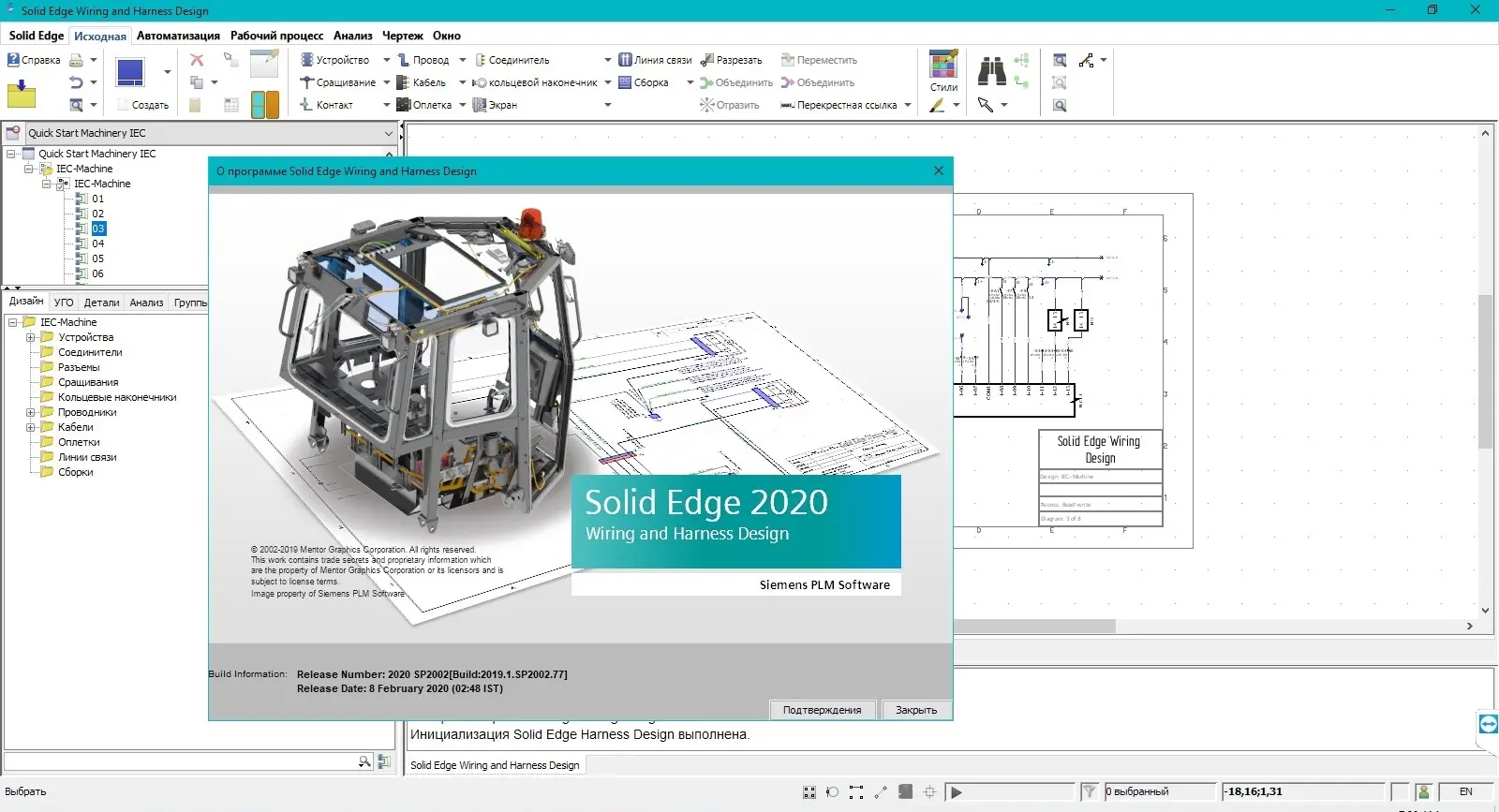
Product: Siemens Solid Edge Electrical Design
Version: 2020 SP2002 (build 2019.1.SP2002.77)
Supported Architectures: x64
Website Home Page : https://solidedge.siemens.com/
Language: multilanguage
System Requirements: PC *
Size: 2.7 Gb
Supported Operating Systems
Solid Edge Wiring and Harness Design clients are supported in the following environments:
- Windows 10 Enterprise or Professional (64-bit only) version 1709 or later (recommended)
- Windows 8.1 Pro or Enterprise (64-bit only)
Solid Edge Wiring and Harness Design servers are supported in the following environments:
- Windows Server 2019 (recommended)
- Windows Server 2016
- Windows Server 2012 R2
Support for maintenance releases (service packs) on these operating systems versions will cease when the manufacturers end general support for them.
Memory (RAM) and Disk Space Requirements
The minimum memory required by Solid Edge Wiring and Harness Design is 4GB. The recommended memory is 8GB or more. Recommended available disk space for the client is 10GB, and 25GB for the server. In standalone configurations where the client and server are on the same machine, these values should be combined. It is recommended to install the embedded database on fast physical storage such as an SSD (solid state drive) array. It is recommended to use striped RAID for the database.
Display Resolution
The client applications require a minimum video resolution of 1024x768 16-bit color, or higher. Recommended video resolution is 1920x1080 or higher. 24-bit color displays are recommended for client machines.
Machine and CPU Requirements
A modern physical or virtual machine with underlying hardware no older than 4 years is recommended with a professional grade CPU having at least two cores. The recommendation intentionally encompasses a wide variety of makes, models, generations, cache sizes, frequencies, memory types and so on due to rapid evolution of hardware available on the market.
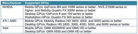
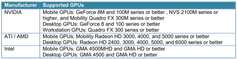
Graphics Processing Unit Requirements
The following graphics processing units (GPU) are required for 3D operations and recommended for 2D operations on both physical and virtual machines.
![Siemens Solid Edge Electrical Design 2020 SP2002]()
Solid Edge Wiring and Harness Design clients are supported in the following environments:
- Windows 10 Enterprise or Professional (64-bit only) version 1709 or later (recommended)
- Windows 8.1 Pro or Enterprise (64-bit only)
Solid Edge Wiring and Harness Design servers are supported in the following environments:
- Windows Server 2019 (recommended)
- Windows Server 2016
- Windows Server 2012 R2
Support for maintenance releases (service packs) on these operating systems versions will cease when the manufacturers end general support for them.
Memory (RAM) and Disk Space Requirements
The minimum memory required by Solid Edge Wiring and Harness Design is 4GB. The recommended memory is 8GB or more. Recommended available disk space for the client is 10GB, and 25GB for the server. In standalone configurations where the client and server are on the same machine, these values should be combined. It is recommended to install the embedded database on fast physical storage such as an SSD (solid state drive) array. It is recommended to use striped RAID for the database.
Display Resolution
The client applications require a minimum video resolution of 1024x768 16-bit color, or higher. Recommended video resolution is 1920x1080 or higher. 24-bit color displays are recommended for client machines.
Machine and CPU Requirements
A modern physical or virtual machine with underlying hardware no older than 4 years is recommended with a professional grade CPU having at least two cores. The recommendation intentionally encompasses a wide variety of makes, models, generations, cache sizes, frequencies, memory types and so on due to rapid evolution of hardware available on the market.
Graphics Processing Unit Requirements
The following graphics processing units (GPU) are required for 3D operations and recommended for 2D operations on both physical and virtual machines.
Siemens Solid Edge Electrical Design 2020 SP2002
Please visit my blog
Added by 3% of the overall size of the archive of information for the restoration
No mirrors please

![Siemens Solid Edge Electrical Design 2020 SP2002]()
Added by 3% of the overall size of the archive of information for the restoration
No mirrors please
Siemens Solid Edge Electrical Design 2020 SP2002