


Autodesk Fusion & Solidworks CAD Basics (CAD Crash Courses)
Autodesk Fusion & Solidworks CAD Basics (CAD Crash Courses)
Published 3/2025
MP4 | Video: h264, 1920x1080 | Audio: AAC, 44.1 KHz
Language: English | Size: 343.18 MB | Duration: 0h 33m
Published 3/2025
MP4 | Video: h264, 1920x1080 | Audio: AAC, 44.1 KHz
Language: English | Size: 343.18 MB | Duration: 0h 33m
Learn Autodesk Fusion & SolidWorks CAD Basics (Modelling - Assembly - Drafting), 2 Different Softwares
What you'll learn
You will learn Autodesk Fusion CAD
You will learn SolidWorks CAD
You will learn Fusion Modelling
You will learn Fusion Assembly
You will learn Fusion Drawing
You will learn SolidWorks Modelling
You will learn SolidWorks Assembly
You will learn SolidWorks Drawing
Requirements
CAD Concept (3D Modelling)
Description
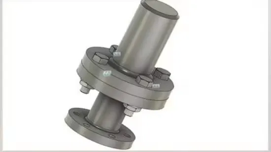
Learn Autodesk Fusion & SolidWorks CAD Basics (Modelling - Assembly - Drafting)Autodesk Fusion 360 and SolidWorks are two of the most popular Computer-Aided Design (CAD) software used in product design, engineering, and manufacturing. Here's a basic crash course to get you started with each of them:Autodesk Fusion 360 Basics:Fusion 360 is a cloud-based CAD tool that integrates multiple stages of the product development process, including design, engineering, and manufacturing.User Interface Overview:Toolbar: Contains tools for sketching, modeling, and managing your design.Browser: Shows the structure of your design with all components, bodies, and sketches.Timeline: Displays a step-by-step history of your design process.Canvas: Where you view and interact with your design.Creating a New Project:Open Fusion 360 and create a new design (File > New Design).Start by creating a 2D Sketch to define the outline of your object (Sketch > Create Sketch).Use basic sketch tools like lines, circles, and rectangles to define your shape.Basic Modeling (Extrusion & Revolve):Extrude: Select a closed profile and use the extrude tool to add depth (Create > Extrude).Revolve: For creating objects like cylinders, select a profile and an axis, and then use the revolve tool (Create > Revolve).Assembly:You can create multiple components and bring them together in an assembly (Assemble > New Component).Use joints to specify how parts move relative to each other.Parametric Design:Fusion 360 allows for parametric design, which means you can define dimensions and relations between objects that will adjust as you change certain parameters.SolidWorks Basics:SolidWorks is another popular CAD tool, well-known for its powerful parametric modeling capabilities, particularly in mechanical design.User Interface Overview:Command Manager: Contains all the tools you need for sketching, features, assemblies, and drawings.FeatureManager Design Tree: Displays your design’s structure, including parts, assemblies, and features.Graphics Area: The main space where you view and interact with your design.Starting a New Part:Open SolidWorks and start a new part (File > New > Part).Create a 2D Sketch on one of the planes (Top, Front, or Right).Use tools like Line, Circle, and Rectangle to define your basic shape.Extruding & Revolving:Extrude: After creating your sketch, use the "Extrude Boss/Base" tool to give your sketch depth (Insert > Boss/Base > Extrude).Revolve: To create symmetric parts, use "Revolve Boss/Base" (Insert > Boss/Base > Revolve).Creating an Assembly:Create a new assembly (File > New > Assembly).Insert parts by selecting them and placing them in the assembly.Use mates (Insert > Mate) to define the relationships and movement between parts (e.g., coincident, concentric).Drawing for Manufacturing:SolidWorks allows you to create detailed drawings from 3D models (File > Make Drawing from Part).Create views like front, top, side, and isometric, and annotate your drawing with dimensions.
Mechanical Engineers,Drafters,CAD Engineers,Production Engineers